Building an electronic timer with transistors is a great project for both hobbyists and professionals. This guide will take you through the basics of making a simple electronic timer. You’ll learn about transistor circuits, which are crucial for precise control and reliable performance.
Creating a simple electronic timer will help you understand electronic components and circuit design better. You’ll learn how to choose the right transistors and make your timer work well. By the end, you’ll know how to build a transistor-based timer circuit and its uses. For more on transistor timer projects, check out this detailed guide or learn how to build a transistor-based LED driver.
Key Takeaways
- This guide focuses on building an electronic timer using transistors.
- Understanding the importance and application of timer circuits.
- Essential components are key to the successful construction of the timer.
- Testing and verification techniques ensure functionality.
- Fine-tuning the timer can enhance precision and stability.
- A variety of timer applications exist across different technologies.
- Exploring future enhancements can advance the timer’s capabilities.
Understanding the Basics of Electronic Timers
Electronic timers are key in managing time in many areas. They help control time with great accuracy. This makes them useful in both home and work settings.
What is an Electronic Timer?
An electronic timer is a tool that measures time and starts actions when needed. It can be made with simple parts like resistors and capacitors. These parts work together to control time.
Importance of Timers in Everyday Applications
Electronic timers are essential in daily life. They are used in home systems, kitchen gadgets, and industrial equipment. For example, they help control when devices turn on after a delay.
People like drag racers also use timers. They help improve performance and reaction times.
Components Required for the Timer
To make an electronic timer, you need several key parts. Each part is important for how well the timer works. Knowing what each part does helps it work better.
Essential Transistors for Timing Circuits
Choosing the right transistor is key for a good timer. The 2N3904 NPN transistor is often used because it has a high gain value of 300. It can handle up to 200mA of current.
For most circuits, using three 2N3904 transistors is best. You also need a relay and other parts to complete the circuit.
Additional Components: Resistors and Capacitors
Resistors and capacitors are crucial for the timer’s timing. Here are some examples:
- 3 resistors at 470kΩ
- 3 resistors at 47kΩ
- 3 capacitors at 470μF each
Resistors control the current, while capacitors set the timing. Changing their values can change how long the circuit stays active.
Power Supply Options for Your Timer
It’s important to power your timer right. A 9V battery is a common choice. It gives enough voltage for the timer’s parts to work well.
Managing power well keeps the circuit stable. This ensures the timer works as it should.

| Component | Type/Value | Purpose |
|---|---|---|
| Transistor | 2N3904 | Used in timing circuits for gain and current regulation |
| Resistors | 3 x 470kΩ, 3 x 47kΩ | Control current flow |
| Capacitors | 3 x 470μF | Establish timing intervals |
| Power Source | 9V Battery | Provides necessary voltage for circuit operation |
| Relay | N/A | Acts as a switch for load control |
Circuit Design for a Simple Timer
This section will give you a clear look at how a timer circuit works. We’ll see how the 555 Timer IC, resistors, capacitors, and an LED work together. A visual guide helps both newbies and seasoned electronics fans understand the setup.
Schematic Diagram of the Timer Circuit
The timer circuit’s electronic schematic shows different setups for timing needs. You’ll find circuits for:
- 1 Minute Timer Circuit
- 5 Minute Timer Circuit
- 10 Minute Timer Circuit
- 15 Minute Timer Circuit
Explanation of the Circuit Elements
Knowing what each part does is key to building the timer. Let’s look at the main components:
| Component | Function |
|---|---|
| 555 Timer IC | Used for timing and pulse generation across different modes: A-Stable, Mono-Stable, and Bi-Stable. |
| LED | Indicates the status of the timer circuit. |
| Capacitor (1000 μF) | Determines timing intervals based on charge and discharge rates. |
| Variable Resistor | Allows for runtime modifications to timing values. |
| Push Button | Initiates timing sequences within the circuit. |
| Resistor | Limits current flow to protect components. |
| Power Supply | Provides the necessary voltage for circuit operation. |
| Connecting Wires | Facilitates coordination among all circuit components. |
Each part is crucial for the timer to work right. The resistor values affect the timer’s timing. For instance, a 1-minute timer needs a 55k ohm resistor, while a 15-minute timer needs 818.2k ohms. This flexibility makes the timer useful for many projects.
Working Principles of Transistors in Timing
Transistors are key in electronic timers, acting as switches to control timing. Knowing how they work is crucial for better timing. The collector, base, and emitter parts of a transistor greatly affect its performance in different setups.
How Transistors Function in Timing Applications
In timing, transistors manage current flow for precise timing. A toggle flip-flop circuit, driven by two transistors, is often used. It changes states with input signals, making a reliable clock pulse. For example, a 60 Hz power supply can be split to make a 1 Hz clock signal for accurate timing.
Types of Transistor Configurations
There are various transistor setups for timing tasks. Key ones include:
- Common Emitter: It boosts voltage, great for switching.
- Common Collector: Acts as an emitter follower, good for signal handling.
- Common Base: Ideal for high-frequency tasks, with special signal handling.
The right setup can make timing circuits more efficient. For example, a Darlington pair network can improve timing by using higher resistors and smaller capacitors. This makes timing more accurate, often within +/- 2%.
| Transistor Configuration | Main Feature | Typical Use Case |
|---|---|---|
| Common Emitter | Voltage amplification | Switching applications |
| Common Collector | High input, low output impedance | Signal buffering |
| Common Base | High-frequency response | RF amplifiers |
Steps to Build Your Timer
Building an electronic timer needs a step-by-step plan for success. Paying attention to details improves your circuit’s performance.
Initial Setup and Configuration
Start by setting up your workspace. Collect all parts like the 2N2222 transistor, resistors, a capacitor, and a 5mm red LED. Use a 9V battery for power. Knowing where each part goes makes the assembly easier.
Assembling the Circuit Components
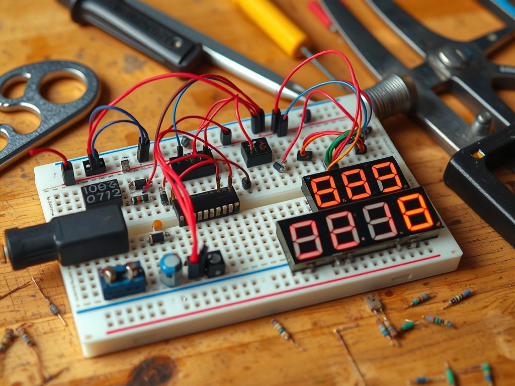
Use the diagram to connect parts on a breadboard. Begin with the capacitor, then the resistors, the transistor, and end with the LED. Remember, each part has its own way of facing. This is crucial for the circuit to work right.
Try different capacitor values to see how it changes the timer’s timing. Making sure parts are in the right place is key to avoiding problems. For more on transistors, check out this guide.
Testing Your Electronic Timer
After you’ve put the timer together, it’s time to test it. It’s crucial that it works right. You’ll need some basic troubleshooting skills to find and fix any problems.
Basic Troubleshooting Techniques
Here are some steps to help you find issues:
- Look for loose connections that could mess up the circuit.
- Make sure the component values match the diagram.
- Double-check the polarity of parts like capacitors and diodes.
Verifying Timer Functionality
First, turn on the power and watch the LED. It should show if the timer is working. For example:
| Condition | LED Response |
|---|---|
| Transistor working | Green LED blinks continuously |
| Shorted transistor | LED not glowing in any half cycle |
| No transistor connection | Green and red LEDs flash alternatively |
If the LED doesn’t act right, go back and check everything again. You can also use voltage drops to see how the circuit is doing.
Testing electronic timers, like the one in this guide, is key for both pros and students. Knowing how to troubleshoot helps you figure out if the timer works well.

Fine-Tuning Your Timer for Precision
Once your timer circuit works right, you can make it better. You can improve both precision and stability. These tweaks are key for consistent results in many projects.
Accurate timing is crucial. It’s needed for simple LED flashes to complex music beats.
Adjusting Timing Intervals
To tweak the timer, change the values of capacitors and resistors. This affects how fast the circuit charges and discharges. For example, bigger capacitors mean longer times, and less resistance means shorter times.
These changes let you tailor the timing for your needs. The importance of these tweaks is huge. They shape how the circuit works.
Enhancing Circuit Stability
To keep the circuit stable, add decoupling capacitors near the power supply. This helps fight off sudden changes that could mess with timing. A stable circuit means better timing and longer-lasting parts.
Being able to stabilize the circuit opens up more advanced uses. It also makes the timer more reliable.
| Component | Effect on Timing | Effect on Stability |
|---|---|---|
| Resistors | Influences charge/discharge rate | Minimal impact |
| Capacitors | Determines timing intervals | Can stabilize fluctuations |
| Decoupling Capacitors | No direct effect | Significantly improves stability |
Being careful with these tweaks really pays off. Each change helps your timer work better. It’s all about getting the results you want from your projects.
Exploring Different Timing Intervals
Electronic timers are versatile and work well in many areas. They depend on specific timing intervals. Knowing the difference between short and long timers helps us use them better for various tasks.
Short vs Long Timing Intervals
Short timers are great for quick tasks. For example, LED flashers need fast on-off cycles to work. On the other hand, long timers are perfect for tasks that take longer, like cooking timers that keep food cooking right.
The choice between short and long timers affects how electronic circuits are designed and work.
Applications for Different Time Settings
Choosing the right timing interval is key for many timer applications. Here’s a table showing different uses based on timing:
| Application Type | Timing Interval | Example Use |
|---|---|---|
| LED Flashers | Short | Creating flashing indicators |
| Cooking Appliances | Long | Automatic shut-off timers |
| Sound Generation | Short | Tone generation circuits |
| Frequency Division | Short | Clock pulse generation |
| Sequential Lighting | Long | Light displays with prolonged transitions |
Understanding timing intervals and their uses helps us tailor electronic timers for our projects.

Integrating Additional Features
Adding more to an electronic timer can make it better to use. Features like a reset function and visual indicators help a lot. They give users more control and clear signs of what’s happening.
Adding a Reset Function
A reset timer lets you start over without unplugging it. This is great for tasks that need quick changes or where timing is key. It makes using the timer easier and more accessible.
Incorporating Visual Indicators
Visual signs, like LEDs, show the timer’s status. They tell you if it’s running, paused, or done. This makes the timer easier to use and more efficient.
| Feature | Description | Benefits |
|---|---|---|
| Reset Function | Resets the timer without power cycling | Increases convenience and accuracy |
| Visual Indicators | LEDs to show timer status | Improves user feedback and accessibility |
Best Practices for Building Electronic Circuits
Building electronic circuits needs careful attention and following certain rules. These best practices improve both the circuit’s function and safety. By avoiding common mistakes, builders can get reliable results.
Safety Precautions to Consider
In electronics, safety is a must. Here are some key precautions:
- Always disconnect power before making adjustments to avoid electric shock.
- Confirm all connections before applying voltage to ensure correct polarity and avoid component damage.
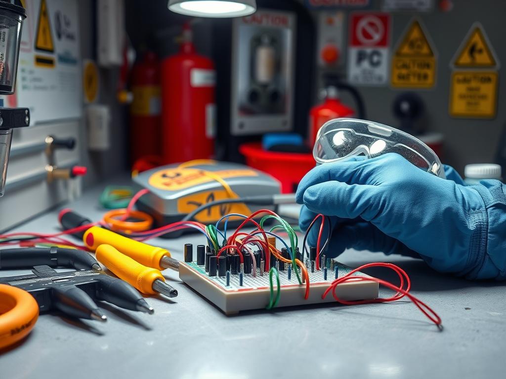
- Use appropriate protective gear, such as gloves and safety goggles, when handling electronic components.
- Choosing the right power sources is crucial; ensure they are suitable for your circuits.
- Regularly check for potential hazards, including frayed wires and overheating components.
Common Mistakes to Avoid
Many builders make mistakes that can be avoided. Here are some tips:
- Misplacing components can lead to circuit failures. Always double-check placement before soldering.
- Poor soldering techniques might cause intermittent connections, affecting circuit performance.
- Overlooking circuit polarity, especially with polarized components like capacitors and diodes, can lead to damage.
- Failing to test circuits at each stage of assembly may result in challenges when troubleshooting later.
- Not utilizing resistor values properly can disrupt function; specific values are crucial for timing circuits.

Following these safety tips and avoiding common mistakes can greatly improve a builder’s success. Mastering safety in electronics ensures your projects are not only functional but also secure. This opens the door to more complex and rewarding projects.
Understanding Timer Applications
Electronic timers play a big role in our daily lives. They help with simple tasks like cooking and complex tech operations. Knowing how timers work helps us see their importance in different areas.
Everyday Uses of Electronic Timers
Timers are used in many ways every day. Here are some examples:
- Cooking: Timers make sure food is cooked just right, avoiding overcooking or undercooking.
- Gardening: Timers help with watering plants, saving water and keeping plants healthy.
- Exercise Routines: Timers help set up workout intervals, making training more effective.
- Reminders: Timers remind us of important tasks and meetings, helping us stay on track.
Advanced Applications in Technology
In tech, timers use advanced tech for better control and function:
- Automation Systems: Timers automate tasks in factories, improving production.
- Smart Home Devices: Timers in smart devices control when things turn on or off, like lights and heat.
- Test Equipment: Timers in test gear help with measurements.
- Signal Processing: Timers manage signal timing in communication systems, ensuring data is sent well.
Learning from Existing Timer Projects
Looking at successful DIY timer projects can teach us a lot. They show us how to make reliable timers with parts like the NE555 IC and transistors. By analyzing these projects, we can learn new ideas and get creative with our own projects.
Review of Successful DIY Timer Projects
Many DIY timer projects are popular among electronics fans. They often use the NE555 timer because it’s easy to use, cheap, and works well. Introduced in 1971, the NE555 IC is used in many things like microwaves and alarm clocks.
Analyzing Design Choices in Projects
When making DIY timers, we choose the right parts and set the timing. Using two transistors is key for making waveforms. Picking the right resistors and capacitors makes the timer more accurate than mechanical ones.
Using different transistors lets us create complex circuits. This allows for many timing options.
| Component | Quantity Needed | Purpose |
|---|---|---|
| NE555 IC | 1 | Timer Control |
| 2N3904 NPN Transistor | 11 | Amplification and Switching |
| 2N3906 PNP Transistor | 9 | Amplification and Switching |
| Resistors (1k ohm) | 2 | Current Limiting |
| Resistors (10k ohm) | 2 | Current Limiting |
| Resistors (4.7k ohm) | 11 | Voltage Divider / Timing Adjustments |
| Bypass Capacitor (100µf) | 1 | Stability in Supply |
By looking at these projects, we can learn a lot about circuit design. It helps us improve our skills and come up with new ideas. For more info, check out this tutorial on 555 Timer Projects.

Future Enhancements for Your Timer
Technology keeps getting better, and so do electronic timers. They’re moving from simple to smart, thanks to digital features. These upgrades use microcontrollers to make timers more flexible and user-friendly.
Introduction to Digital Timer Features
Digital timers offer better control over timing. You can set exact times and adjust settings easily. They’re great for home use and work well in big projects too.
Potential Upgrades with Microcontrollers
Microcontrollers make timers smarter. They let you program them for different tasks. This means you can change settings, add sensors, or connect to the internet.
Using these new technologies shows how far electronics have come. With more transistors, devices work faster and use less power. For tips on making oscillators stable, check out this resource.
| Feature | Description | Advantages |
|---|---|---|
| Digital Control | Allows precise interval settings and electronic adjustments. | Enhanced accuracy and user flexibility. |
| Programmability | Microcontrollers enable customized functionalities. | Greater operational versatility and automation. |
| Remote Access | Integration with IoT for off-site control. | Convenience and improved monitoring capabilities. |
Conclusion: The Value of Building Electronic Timers
Building electronic timers boosts your skills in electrical engineering. It’s a great way to learn by doing. The LM556CN, a dual timer chip, shows how these projects can make DIY electronics better.
By using resistors, capacitors, and more, you can make timers that do many things. They can flash LEDs or sound alarms. This is just the start of what you can do with timing circuits.
Recap of Key Takeaways
This project has taught you a lot about making circuits. You’ve learned about the right resistor and capacitor values. This knowledge helps you make timers that work well.
Timers are useful because you can change them to do different things. They’re a great way to learn and get ready for more complex projects.
Encouragement to Experiment Further
Keep trying new things with circuits. Try different resistor and capacitor values. Or, see what happens when you add microcontrollers.
These experiments will make you better at electronics. They’ll also help you think creatively. This is how you’ll make new technology in the future.


