Making a homemade voltage inverter is exciting for both hobbyists and professionals. You can use transistors to turn ideas into real, working devices. This hands-on method is great for making things like battery backups and off-grid power solutions.
By using transistors, you can change low input voltages into higher ones. This makes your homemade voltage inverter very useful for many people.
Key Takeaways
- Understanding different inverter circuits enhances practical skills.
- Choosing the correct transistors like MOSFETs is crucial for efficiency.
- The oscillator board plays a vital role in voltage transformation.
- Regular maintenance ensures longevity and performance of inverters.
- Testing your designs can prevent potential failures and improve reliability.
Understanding Voltage Inverters
Voltage inverters change direct current (DC) into alternating current (AC). This is key for running many electrical devices. They can take a low voltage like 12V DC and turn it into a high voltage AC, usually around 220V.
These devices are vital in many areas, especially in renewable energy like solar power and portable power sources.
What is a Voltage Inverter?
A voltage inverter uses technology and parts to convert efficiently. It has basic elements like transformers and power devices like N-channel MOSFETs. Lead acid batteries are also used.
The inverter’s oscillator circuit is crucial. It switches the DC into the transformer’s primary winding. IC 4060 or 555 ICs are used to make efficient oscillators. This makes the inverter reliable and effective.
These inverters can produce 50Hz or 60Hz output frequencies. This depends on the local utility standards.
Importance of Voltage Inverters
Knowing about voltage inverters is more than just technical knowledge. It’s essential for engineers and hobbyists in power electronics education. These devices manage power efficiently and are crucial in backup power and renewable energy systems.
For example, a power inverter can change a 12V battery’s output into AC power. This lets devices work during power outages. For DIY projects, this guide on power inverters offers useful information.
Basic Principles of Voltage Inversion
Learning about voltage inversion is key for electrical engineering students. It involves the work of several inverter parts. These parts, like transistors and transformers, help turn DC into stable AC.
How Voltage Transformation Works
Voltage transformation changes DC to AC and adjusts the voltage level. Inverter circuits use a two-step process. First, they invert the current, then transform it.
A good inverter can handle low currents and power over 300 watts. They work well, with efficiencies over 85%. This makes them great for many uses.
Key Components Involved
The success of voltage inverters depends on their parts. Important components include:
- MOSFETs: These transistors act as switches, controlling the flow of electricity through the inverter.
- NPN Transistors: Used for signal amplification, facilitating efficient conversion from DC to AC.
- Transformers: Essential for stepping up or stepping down voltage levels, which allows the inverter to cater to various load specifications.
- Coils: The inverter’s coils are critical; for instance, the windings of L1 and L2 are made from Φ1.62mm enameled wires with 50 turns, while L3, L4, and L5 comprise Φ0.53mm enameled wires with 12, 12, and 945 turns respectively.
This careful arrangement of parts keeps the output voltage steady. Understanding voltage transformation helps create strong inverter designs.
Selecting the Right Transistors
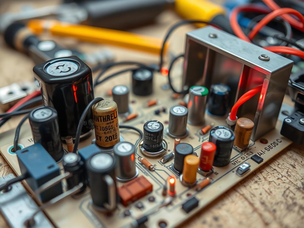
Choosing the right transistors is key for voltage inverters to work well. It’s important to know about the different types, like bi-polar junction transistors (BJTs) and metal-oxide field-effect transistors (MOSFETs). Each type has its own strengths for different uses.
Types of Transistors for Inverters
NPN and MOSFET transistors are often used in inverters. NPN transistors, like the BC337 or 2N3904, have three parts: collector (C), base (B), and emitter (E). They help control current flow well, like a water valve.
MOSFET transistors, like the IRF3205 and IRLB4132, are better for high currents and fast switching. This makes them great for inverters needing to be efficient.
Factors to Consider in Selection
When picking transistors for an inverter, consider a few things for the best results:
- Voltage Ratings: Make sure the transistor can handle the circuit’s voltage.
- Current Capacity: Check if the transistor can handle the maximum current without getting too hot.
- Switching Speed: Choose transistors that switch quickly, especially for high-frequency tasks.
Choosing the right transistors and knowing about NPN and MOSFET transistors makes inverters work better. This ensures they are safe and efficient in many power uses.
| Transistor Type | Common Models | Key Specifications |
|---|---|---|
| NPN | BC337, 2N3904 | Operating Voltage: Up to 45V Max Current: 800mA |
| MOSFET | IRF3205, IRLB4132 | Operating Voltage: Up to 55V Max Current: 110A |
Designing Your Inverter Circuit
Creating a DIY inverter circuit needs careful planning. A good layout is key to less energy loss and better performance. Things like heat management, precise component placement, and wire routing are crucial.
Essential Circuit Layout Considerations
For a homemade inverter to work well, consider these layout tips:
- Make sure components have enough space for cooling.
- Put power transistors near their heat sinks for better cooling.
- Route wires to cut down on electrical noise and interference.
- Use a star grounding technique to prevent ground loops and improve stability.
By focusing on these points, you can avoid common mistakes. This will make your inverter more reliable and efficient.
Common Circuit Design Errors to Avoid
Many mistakes can happen when making a DIY inverter circuit. Knowing these common errors is important:
- Poor grounding can cause voltage issues and noise.
- Not having good cooling can lead to overheating and failure.
- Bad component placement can mess up signal flow and efficiency.
- Not leaving enough space for wiring and connections can cause clutter.
Spotting these problems early can save a lot of time and effort. For more tips on designing efficient circuits, including transistor roles, check out effective power circuit design practices.
Required Tools and Materials
Building a homemade voltage inverter needs the right tools and materials. This knowledge helps DIY fans make a good inverter. It changes 12V DC to 220V AC. Here, we’ll talk about the tools you need and the materials that last.
Tools You’ll Need for Construction
The right tools are key for a successful inverter project. Here’s a list of what you’ll need:
- Soldering iron
- Wire strippers
- Multimeter
- Wire cutters
- Pliers
- Breadboard or PCB for layout
These tools help with soldering and checking connections.
Recommended Materials for Durability
Choosing durable materials is crucial for your inverter’s life and reliability. Important parts include:
| Component | Specifications |
|---|---|
| 5-pin plug socket | Standard for power connections |
| AC switch | For controlling power input |
| Transistors | Types include NPN and PNP |
| SPST switches | Used to turn the circuit on/off |
| 555 timer IC | For pulse generation |
| Capacitors | 104pF and 4700uF for smoothing |
| IRFZ44N MOSFETs | High-speed switching |
| Transformer | 12-0-12/3Amp for stepping voltage |
| 7805 voltage regulator | To maintain a steady output |
These parts work together for the best performance and safety. For more on creating stable oscillators, check out this resource.
Building the Inverter: Step-by-Step Guide
Building a homemade inverter needs careful planning and execution. This guide will walk you through the process, starting with the initial setup and moving on to wire connections. Making sure these connections are done right is key for a safe and working inverter.
Initial Setup and Wire Connections
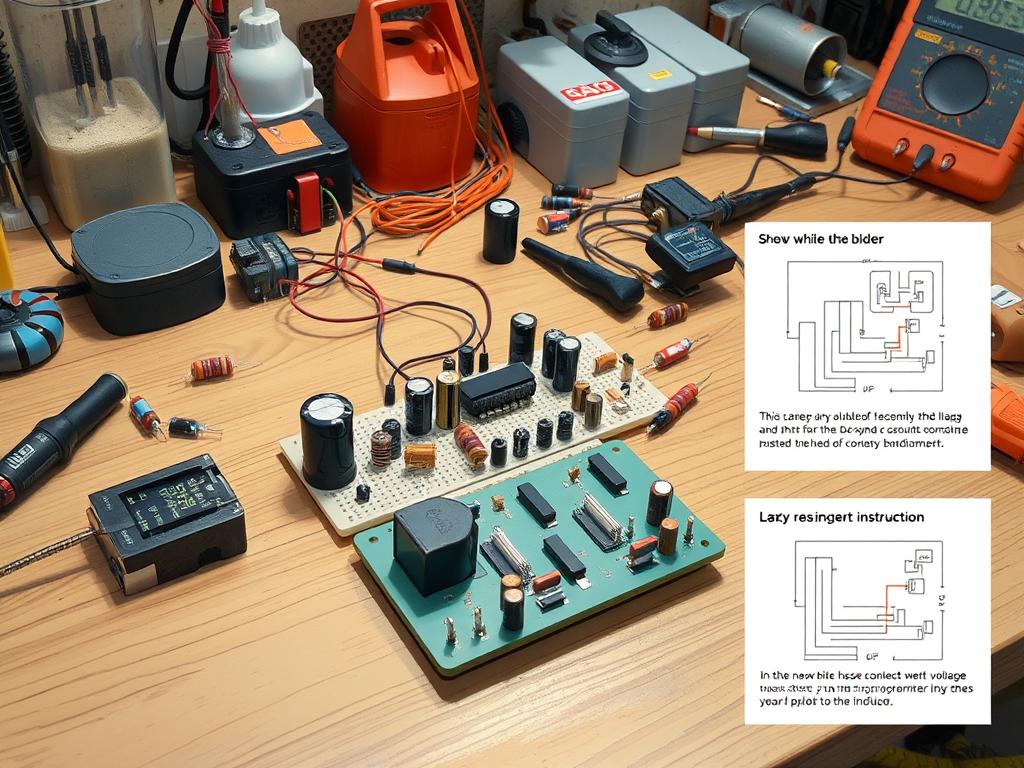
Start your inverter project by getting all the parts you need. This includes the 12-0-12/3Amp transformer, BC547 transistor, and more. First, set up a clear workspace and gather your tools like pliers, wire cutters, and soldering equipment. Here’s how to make the wire connections:
- Prepare the wires: Cut the wires to the right lengths for your circuit.
- Strip the ends: Take off the insulation from the wire ends for better connections.
- Connect components: Connect the DC source, oscillator, amplifier, and step-up transformer to make the inverter circuit.
- Solder joints: Solder the wire connections carefully to make them last longer and work better.
Testing Your Connections for Safety
After you’ve made the wire connections, it’s time to test them. This step is important to make sure everything works right and to keep it safe:
- Visual Inspection: Look for any loose wires or bad connections.
- Use a Multimeter: Check the voltage in the circuit to see if it’s in the right range.
- Power Test: Plug the inverter into a load and watch how it does. Listen for strange sounds or feel for too much heat.
- Follow Safety Protocols: Make sure to disconnect any bad loads and don’t use it with medical devices.
For more info on parts and tips for building, check out this guide. By following these steps, you’ll not only make a reliable inverter but also have a better building experience.
Troubleshooting Common Issues
Troubleshooting is key to a homemade voltage inverter’s success. Knowing how to spot common inverter issues keeps systems running smoothly. This includes problems like overheating, short circuits, or unstable output.
Identifying Common Problems in Inverters
During use, inverters can face several issues. Spotting these early helps fix problems quickly. Here are some common ones:
- Overheating: This could mean parts are too small or not cooling well.
- Short Circuits: Often caused by wiring mistakes or damaged parts.
- Output Instability: Fluctuating voltage can come from wrong transistor or capacitor settings.
Effective Solutions for Troubleshooting
Fixing common inverter problems starts with a careful check and repair plan. Here are some steps:
- Measure Voltages: Use a multimeter to check voltages, especially for transistors. Make sure the base-to-emitter voltage is about 0.7 V and the collector-to-emitter is around 0.3 V when saturated.
- Check Resistance Values: Wrong resistance can cause big changes in base current, possibly harming the device. Use an ohm-meter to check resistor values before adding them.
- Voltage Level Evaluation: Regularly check voltage levels across the circuit to find problems.
Using these troubleshooting methods helps builders solve problems well. This keeps the homemade inverter working right. Keeping voltage levels and component health in check is crucial for a reliable inverter system.
Ensuring Safety During Construction
Safety is key when making homemade voltage inverters. Following electrical safety rules helps avoid accidents and makes the project a success. Knowing how to handle electronic parts safely is crucial. It keeps you safe and makes sure the electronics work right.
Electrical Safety Precautions
Here are important safety steps for electronics projects:
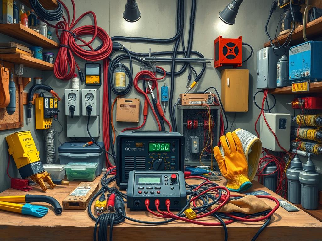
- Use insulated tools to avoid electrical shock.
- Wear insulated gloves and safety goggles to protect yourself.
- Keep work areas dry and safe to avoid electrical shock.
- Check voltage and current ratings before connecting parts to avoid short circuits.
- Use proper grounding to safely handle stray currents.
Best Practices for Handling Components
Handling electronic parts right is key for safety and function:
- Use anti-static wrist straps to prevent static damage to sensitive parts.
- Keep parts organized on a work surface to avoid mistakes.
- Solder parts carefully to avoid short circuits.
- Store spare parts and tools in labeled containers for easy access.
- Check tools regularly to ensure they work properly and prevent accidents.
Optimizing Your Inverter’s Performance
Improving an inverter’s efficiency is key for off-grid living and small boat use. There are efficiency enhancement techniques to help. By using the right methods, your system will work better and save energy.
Techniques for Enhancing Efficiency
Choosing the right parts is crucial for a good inverter. High-quality transistors and capacitors are essential. Also, how you lay out the inverter circuit matters a lot. A good layout helps power flow smoothly.
- Use the right transistors for your load.
- Make your circuit layout efficient to cut down on losses.
- Check and replace old parts to keep your inverter running well.
Monitoring and Adjusting Output
Keeping an eye on your inverter’s output is key. Use tools like multimeters and oscilloscopes to check its performance. This lets you make adjustments on the fly to improve efficiency. Off-grid users often turn off their inverters when not in use to save energy.
| Device Type | Power Requirement (W) | Inverter Efficiency (%) |
|---|---|---|
| Microwave | 800 | 85 |
| Laptop | 60 | 90 |
| Refrigerator | 150 | 80 |
| Radio | 10 | 95 |
Knowing the real efficiency of your inverter can lead to better choices. Dual inverters are great for handling different power needs. They help your inverter work better for all your devices. For more tips, check out PWM circuits on using transistors.
Applications of Homemade Voltage Inverters
Homemade voltage inverters have many uses, especially in homes and industries. They are flexible and can meet specific power needs. Knowing how they work helps us see how they improve energy use and reliability.
Use Cases in Residential Settings
In homes, voltage inverters are used for many things. Homeowners use them to:
- Charge electric vehicle batteries.
- Power lights when the power goes out.
- Run important appliances without the grid.
- Help with solar energy systems.
Home inverters usually have a power range of 300W to 1000W. This range meets most household needs for power and reliability.
Industrial Applications and Benefits
In industries, homemade voltage inverters help improve performance and cut costs. They are used for:
- Powering machinery without the grid.
- Boosting automation systems for better productivity.
- Providing backup power during outages.
DIY industrial inverters can go over 2000W. This is cheaper than buying commercial ones, which are pricier. Using parts like the EGS002 inverter driver module makes these inverters affordable. For more info, check out this guide on designing inverters.
Maintenance Tips for Longevity
Keeping your homemade inverter in good shape is key for top performance and long-lasting electronics. Regular checks and maintenance tasks boost your inverter’s life and prevent sudden breakdowns. Watch out for certain signs to catch problems early and avoid big repairs. Here are some important practices and signs to watch.
Regular Check-Ups and Maintenance Tasks
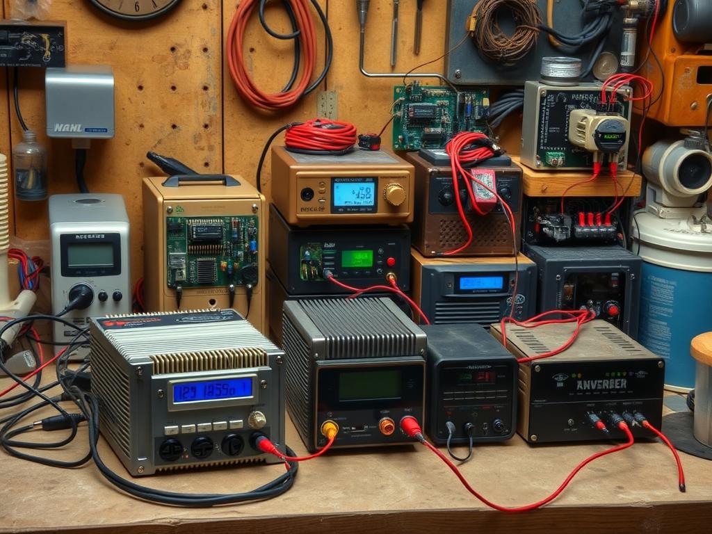
Do regular checks on your inverter system to keep it running well. Follow these inverter maintenance tips:
- Check all electrical connections for any signs of wear or corrosion.
- Monitor voltage and current levels using a compatible energy meter to ensure they remain within prescribed limits.
- Inspect circuit breakers, ensuring they are appropriately rated; for example, 25A AC circuit breakers should be tested periodically.
- Evaluate the performance of surge protective devices (SPDs), which provide critical protection against lightning and grid surges.
- Utilize thermal inspection tools, like an Optris camera, to detect unusual heat generation in components.
Signs Your Inverter Needs Repair
Knowing when your inverter needs repair can save time and money. Look out for these signs:
- Frequent tripping of circuit breakers could indicate overloading or wiring issues.
- Unusual heat generation or strange noises could signal internal faults in components.
- Inconsistent energy output may suggest that the inverter is not functioning adequately.
- Visible corrosion or damage on connectors might require immediate attention to prevent further issues.
By following these tips, you can make your inverter last longer and work better. This means you’ll need to fix it less often and save money. Keeping your inverter in good shape also means you’ll have a reliable energy source for a long time. For more tips on improving electronic systems, check out best practices related to transistors.
Comparing Homemade vs. Commercial Inverters
Choosing between homemade and commercial inverters depends on several factors. DIY solutions have their pros and cons, helping both hobbyists and professionals make informed choices. Understanding these differences is key to picking the right inverter for your needs.
Pros and Cons of DIY Inverters
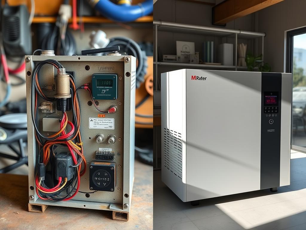
Many people like DIY inverters because they can be customized and are often cheaper. Building an inverter yourself lets you tailor it to your exact needs. DIY inverters are also known for their efficiency and ease of making.
For example, a simple DIY inverter can turn DC into AC using MOSFETs. This can produce up to 3000W of power, especially with sine wave designs.
- Advantages of DIY Inverters:
- Cost savings compared to commercial products.
- Customization to specific project requirements.
- High output capabilities, with some reaching up to 3000W.
- Disadvantages of DIY Inverters:
- Potential inefficiencies, especially at low loads.
- Complexity in design can lead to errors.
- Lack of warranty or support compared to commercial options.
When to Consider Purchasing Instead
For those who prefer not to DIY, buying an inverter is a reliable option. Commercial inverters, starting at around AU$300 for 150W, offer warranty support and consistent performance. They are designed to handle low currents well, with some using about 400mA (~4.8W) in standby.
| Feature | Homemade Inverters | Commercial Inverters |
|---|---|---|
| Cost | Generally lower, DIY materials | Around AU$300 for 150W |
| Customization | Highly customizable | Limited customization |
| Efficiency | Variable, up to 87% efficiency | Typically efficient, designed for stability |
| Power Output | Varies, up to 3000W | 150W and up, often exceeding 600W |
| Support | No official support | Warranty and customer service available |
Both homemade and commercial inverters have their benefits. Understanding these can help you choose the best option for your needs. For more information on components like IGBTs, check out this resource.
Real-Life Success Stories
DIY inverter success stories show the creativity and skills of those who make their own solutions. These stories tell of people overcoming technical hurdles. They lead to new designs and useful applications.
Featured Projects by DIY Enthusiasts
The High Voltage Generator II circuit is a great example. It uses a 9V battery to make about 25 VAC. This shows how people can improve their projects by changing parts.
For example, swapping a 100 µF capacitor for a 470 µF one made a big difference. It shows how picking the right parts is key to better performance.
Another project is a mechanical multivibrator. It makes around 120 VAC from a car lighter jack. This shows a practical solution for low-power needs.
Building DIY projects can be tough, especially finding the right parts. Users on forums share their experiences. One person had to use different capacitors because the ones they needed were hard to find.
Lessons Learned from Inverter Projects
Many projects face challenges, like overheating issues with the STP60NF06FP MOSFET. This shows the need for good cooling systems. Also, the failure of a diode to stop sparks in the relay circuit shows the complexity of working with inductive loads.
People often talk about the shape of the output waveform. They wonder if it’s square, modified, or pure sine. These discussions help us understand the details of inverter performance.
Feedback from projects helps improve designs. It makes future projects more reliable. Sharing what we learn from inverter projects helps the DIY community grow. It creates a place where everyone can learn and innovate together.
| Project Feature | Details | Key Takeaway |
|---|---|---|
| High Voltage Generator II | Produces 25 VAC from a 9V battery | Effective component enhancements can boost performance |
| Mechanical Multivibrator | Generates ~120 VAC from a 12 VDC input | Real-world applications can provide practical solutions |
| Component Substitutions | Used aluminum electrolytic instead of tantalum capacitors | Component availability can affect project success |
| Thermal Management Issues | Overheating MOSFET in prototypes | Importance of thermal management in circuit design |
| Output Waveform Confusion | Questions about output types (square vs. sine) | Understanding waveforms critical to performance expectations |
Common Mistakes to Avoid in Design
Designing a voltage inverter needs careful thought and detail. Many beginners make common mistakes that can stop their projects. These mistakes often lead to devices that don’t work well. It’s key to know these mistakes and how to fix them to improve your work.
Frequent Pitfalls for Beginners
Beginners often miss important steps in design. Here are some common mistakes newbies make when building inverters:
- Not planning for DC bias current return paths in AC-coupled designs, causing problems.
- Ignoring thermal management, leading to overheating and possible failure.
- Not using high-value resistors between op-amp input and ground, causing offset voltage issues.
- Assuming resistor matching in in-amp circuits without checking, leading to offset-voltage errors.
- Connecting high-impedance sources directly to in-amp reference pins, causing big errors.
Solutions to Overcome Design Challenges
Fixing these problems is crucial for a successful inverter design. Here are some ways to overcome these challenges:
- Use a resistor between the op-amp input and ground, 100,000 ohms to 1 Mohm, to reduce offset voltage.
- In in-amp circuits, add high-value resistors between each input and ground to fix bias-current return path issues.
- To lower offset-voltage errors, add a third resistor, about 1/10th the value of the others, between in-amp inputs.
- Put a low-power op-amp buffer between the voltage divider and in-amp’s reference input for better impedance matching.
- Learn about Power-Supply Rejection (PSR) to ensure the inverter works well despite supply voltage changes.
Conclusion: Enhance Your DIY Skills
Improving your DIY skills in electronics can make you understand circuits better. Projects like making homemade voltage inverters give you hands-on experience. They also boost your creativity and problem-solving skills.
By working on these projects, you move from simple parts to more complex electronics. This journey helps you grow technically and builds your confidence in designing circuits.
Encouragement for Future Projects
Use what you’ve learned to start new projects. There are many projects out there, from simple Arduino setups to complex designs. Keep trying new things and learning to improve your DIY skills in electronics.
Don’t be afraid to check out resources on platforms with lots of electronics resources for all levels.
Resources for Further Learning
Many platforms offer tutorials, help finding parts, and community support for your projects. With so many chances to learn, like making water level controllers or LED projects, you can dive deep into electronics. Being dedicated to learning electronics helps both newbies and experts to innovate and create.


